Encoder:
It is a combinational Logic Circuit that converts one number in to another. It has 2n input lines and n output lines. Output lines in an Encoder are decided on the basis of the highest digit of the input number system.
example:
In an Octal Number System the highest octal digit is 7, whose binary equivalent is 111, which requires 3 bits to get stored, hence we have 3 output lines to represent each of its binary digits. So the maximum number of output lines for an Octal to Binary Encoder is 3.
In an Octal Number System the highest octal digit is 7, whose binary equivalent is 111, which requires 3 bits to get stored, hence we have 3 output lines to represent each of its binary digits. So the maximum number of output lines for an Octal to Binary Encoder is 3.
Similarly, in Decimal Number System, the highest digit is 9 whose binary equivalent is 1001, which requires 4 bits to get stored, hence we have 4 output lines to represent each of its binary digits. So the maximum number of output lines for a Decimal to Binary Encoder is 4.
Following are the types of encoder.
a) Octal to Binary Encoder (8 input and 3 output lines)
b) Decimal to Binary Encoder (10 input and 4 output lines)
a) Octal to Binary Encoder (8 input and 3 output lines)
b) Decimal to Binary Encoder (10 input and 4 output lines)
c) Hexadecimal to Binary Encoder (15 input and 4 output lines)
Octal to Binary Encoder:
It has 8 input lines and 3 output lines for each of the octal digits.
Truth Table for Octal to Binary Encoder
|
Input |
Output |
||
|
E2 |
E1 |
E0 |
|
|
0 |
0 |
0 |
0 |
|
1 |
0 |
0 |
1 |
|
2 |
0 |
1 |
0 |
|
3 |
0 |
1 |
1 |
|
4 |
1 |
0 |
0 |
|
5 |
1 |
0 |
1 |
|
6 |
1 |
1 |
0 |
|
7 |
1 |
1 |
1 |
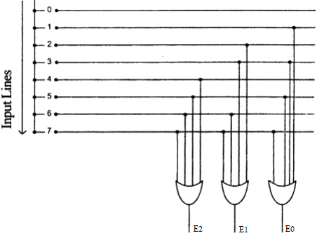
Logic Circuit Diagram of Octal to Binary Encoder:
To design the logic circuit diagram you have to connect the input lines to those gates which has 1 as its value in the output column of the truth table. For example connect input line 6 to output gates E2 and E1 as in the truth table E2 and E1 has value 1 against input 6. Input line 0 is not connected to any output gate as all its output values in the truth table are 0. In the same way all input lines are connected.
Decimal to Binary Encoder:
It has 10 input lines and 4 output lines for each of the Decimal digits.
Truth Table for Decimal to Binary Encoder
|
Input |
Output |
|||
|
E3 |
E2 |
E1 |
E0 |
|
|
0 |
0 |
0 |
0 |
0 |
|
1 |
0 |
0 |
0 |
1 |
|
2 |
0 |
0 |
1 |
0 |
|
3 |
0 |
0 |
1 |
1 |
|
4 |
0 |
1 |
0 |
0 |
|
5 |
0 |
1 |
0 |
1 |
|
6 |
0 |
1 |
1 |
0 |
|
7 |
0 |
1 |
1 |
1 |
|
8 |
1 |
0 |
0 |
0 |
|
9 |
1 |
0 |
0 |
1 |
Logic Circuit Diagram of Decimal to Binary Encoder:
Hexadecimal to Binary Encoder:
It has 16 input lines and 4 output lines for each of the Hexadecimal digits.
Truth Table for Hexadecimal to Binary Encoder
|
Input |
Output |
|||
|
E3 |
E2 |
E1 |
E0 |
|
|
0 |
0 |
0 |
0 |
0 |
|
1 |
0 |
0 |
0 |
1 |
|
2 |
0 |
0 |
1 |
0 |
|
3 |
0 |
0 |
1 |
1 |
|
4 |
0 |
1 |
0 |
0 |
|
5 |
0 |
1 |
0 |
1 |
|
6 |
0 |
1 |
1 |
0 |
|
7 |
0 |
1 |
1 |
1 |
|
8 |
1 |
0 |
0 |
0 |
|
9 |
1 |
0 |
0 |
1 |
|
10 (A) |
1 |
0 |
1 |
0 |
|
11 (B) |
1 |
0 |
1 |
1 |
|
12 (C) |
1 |
1 |
0 |
0 |
|
13 (D) |
1 |
1 |
0 |
1 |
|
14 (E) |
1 |
1 |
1 |
0 |
|
15 (F) |
1 |
1 |
1 |
1 |
Logic Circuit Diagram of Hexadecimal to Binary Encoder:


No comments:
Post a Comment